Suppose you are laying out an AT10 timing belt drive in a packaging machine and the drawing only has 55 mm of space for a return idler. A 50 mm smooth-back idler seems to fit, but if the idler rides on the belt teeth instead, the same location becomes a failure waiting to happen. The belt needs to bend around a minimum radius, and the idler pulley size is the dimension that creates that radius. In practical terms, an AT10 belt with steel tension cords should not be wrapped over an idler smaller than 50 mm on the smooth back, and not smaller than 120 mm when running on the teeth. These values are not luxuries: they protect the tension members and the tooth-to-cord bond from premature fatigue. This guide walks you through the reasoning, the typical numbers, and how to apply them in a real drive.
AT10 Profile and Minimum Bend Radius Basics
AT10 is a 10 mm pitch trapezoidal timing belt profile commonly used in industrial drives that need accurate indexing, repeatable positioning, and moderate power transmission. The pitch line is the imaginary circle inside the belt where the tension cords run. When the belt bends around a pulley or idler, the cord layer is forced to accommodate the difference between the outer and inner surfaces of the bend. If the bend radius is too tight, the steel cords experience high alternating strain every time they pass that element.
The minimum bend radius is easier to understand when you think of a simple idler. A cylindrical idler creates a bend radius equal to roughly half of the idler diameter. A 50 mm smooth-back idler produces a 25 mm bend radius, while a 120 mm tooth-side idler produces a 60 mm bend radius. The tooth-side value is larger because the belt tooth root and the cord bond are more sensitive to flexing and pinch forces than the smooth back surface.
This line chart shows the relationship between idler diameter and flexural strain on the tension cords. The curve drops steeply in the 20 to 60 mm range, which means small pinions and idlers create a big fatigue penalty. Above 100 mm the curve becomes flatter, so an AT10 tooth-side idler at 120 mm is already on the safe plateau. If you reduce the idler from 50 mm to 40 mm, the increase in strain is much larger than the change in envelope size suggests. That is why manufacturer tables specify a minimum idler diameter and why experienced designers treat it as a strict limit. A line chart is a good way to explain the fatigue trade-off to a machine builder before the prototype is cut.
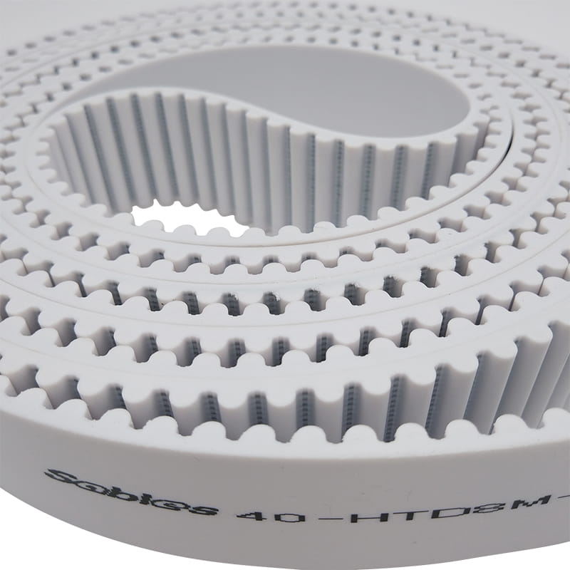
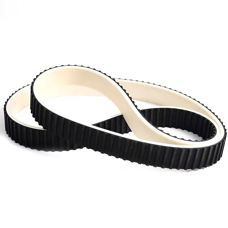
Many AT10 belts are produced in cast polyurethane because the material resists abrasion and keeps its tooth profile under repeated flexing. For drives that need that combination of properties, a polyurethane AT10 belt is a common starting point.
When you choose a polymer body, confirm that the supplier minimum idler values match your cord specification, because the cord is the part that actually sets the bend limit.
Reference Values for AT10 Idler Pulley Size
Most AT10 design tables list three numbers: minimum pulley teeth, minimum idler diameter on the smooth back, and minimum idler diameter on the belt teeth. The values below reflect standard steel-cord AT10 belts used in industrial drives. They are a safe starting point but not a substitute for a manufacturer-specific datasheet.
Typical minimum design values for standard steel-cord AT10 timing belts. Confirm the values with the belt supplier before finalizing a drive layout.
Parameter
Minimum value
Practical note
Minimum pulley teeth
15
Gives a pitch diameter close to 48 mm.
Minimum smooth-back idler diameter
50 mm
Use when an idler contacts the outside surface.
Minimum tooth-side idler diameter
120 mm
Use when an idler contacts the belt teeth.
Minimum bend radius on smooth back
25 mm
Approximately half of the 50 mm idler diameter.
Minimum bend radius on tooth side
60 mm
Approximately half of the 120 mm idler diameter.
The horizontal bar chart makes it easy to compare the three diameter limits that will fit under the hood of most machines. Notice that the drive pulley at 15 teeth is only slightly smaller than the 50 mm smooth-back idler limit. The tooth-side idler is the largest restriction, so it is usually the dimension that determines whether a belt path can fit into a compact housing. If your layout passes the tooth-side idler check, the smooth-back idler and pulley are often already acceptable. This is why engineers are told to draw the entire belt path, including idlers, before ordering pulleys. The 120 mm bar is not an arbitrary safety factor; it represents the point where the belt tooth profile and cord bond have a reasonable margin.
What Happens When the Bend Radius Is Too Small
When an AT10 belt is forced around a radius smaller than the minimum, the first signs of damage are often not visible on the belt surface. The steel cords inside begin to work-harden and crack from the inside as they are flexed repeatedly over a sharp curve. At the same time, the tooth root on the belt flexes aggressively and can open up at the base. The belt may also ride slightly differently on the idler, producing noise and vibration that slowly wears the pulley flange. In a production machine, the usual result is a belt that looks healthy on a Friday and then snaps, skips teeth, or delaminates at the worst possible moment.
This column chart compares the relative flex life of an AT10 belt under three idler scenarios. Undersizing the tooth-side idler by 20 mm can cut belt service life by nearly half when compared with a generous layout. Keeping the idler exactly at the minimum value gives acceptable life, but there is little room for belt-length variation or misalignment. Oversizing the idler by 20 percent costs a little space but buys a much larger safety margin. The chart also explains why experienced machine builders do not try to save 5 mm of envelope space by reducing an idler from 120 mm to 100 mm. The life difference is too large to justify the small gain in packaging.
Idler Pulley Size and Placement Rules
Once you know the minimum diameter, choose the idler bearing and pulley material carefully. An idler that runs on the belt back should be smooth and slightly crowned to help track the belt without adding friction. An idler that runs on the belt teeth should use a profile matched to the AT10 tooth geometry; a flat idler on the teeth can pinch the tooth pockets and accelerate wear. A common rule of thumb is to make the smooth-back idler diameter at least equal to the drive pulley pitch diameter, which for a 15-tooth AT10 pulley means about 50 mm.
Smooth-back idler: minimum 50 mm diameter, with a crowned or flat face depending on belt width.
Tooth-side idler: minimum 120 mm diameter, with an AT10-compatible tooth profile.
Place the idler on the slack span whenever possible so it does not add unnecessary load to the tight side of the drive.
Avoid placing an idler immediately at the entry point of a small pulley, because the combined bend can exceed the material limit.
Check the pulley flange height and belt width combination to prevent edge wear and tracking issues.
Idler position is just as important as idler size. A correctly sized idler in the wrong position can create excessive belt preload, increase bearing load, or force the belt into an S-shaped path. Keep the wraps as clean as possible and give the belt enough straight span between pulleys for the flex to recover.
AT10 Material Choice and Its Influence on Bend Limits
AT10 belts are available in different body materials, and the body compound affects tooth rigidity, abrasion resistance, and heat tolerance. For minimum bend radius, however, the tension cord is the main controlling element. A steel-cord belt will behave differently from a glass-cord belt even when the tooth profile is identical. The body material still matters because it determines whether the tooth root can survive repeated flexing without cracking.
The radar chart is a useful way to compare the general characteristics of rubber and polyurethane AT10 belt constructions. Polyurethane usually shows higher abrasion resistance and more rigid teeth, which helps in dirty or high-torque positioning drives. Rubber belts often give better heat resistance and a quieter engagement in lower-speed applications. For minimum bend radius, the cord material matters more than the body compound, because both constructions rely on steel or glass tension members. Therefore, you should not choose a rubber belt simply because it feels more flexible when the limiting factor is still the cord. Use this chart as a selection checklist and then confirm the final choice with the supplier flex-fatigue data.
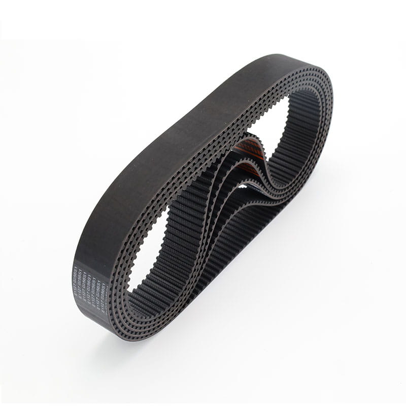
For equipment running in hot environments or where vibration damping is important, a rubber timing belt can be a practical alternative to polyurethane. The same minimum pulley and idler rules still apply, but the supplier should verify the exact values for the chosen rubber compound.
In both cases, request test reports that show flex fatigue under dynamic load rather than only static tensile strength.
Final Design Checks and Installation Notes
Once the belt path is drawn on paper or in CAD, run through a short checklist before ordering parts. The AT10 minimum bend radius is not a hidden spec reserved for engineering specialists, but it must be checked at every wrapped element in the drive.
Verify that every pulley and idler meets the AT10 minimum tooth count and diameter limits.
Confirm whether each idler contacts the smooth back or the belt teeth, and apply the correct minimum value.
Keep the minimum bend radius at least 25 mm on the smooth back and at least 60 mm on the belt teeth.
Place tensioners and idlers on the slack span whenever possible to reduce the additional load on the belt.
Check the pulley flange height, belt width, and center distance before finalizing the design.
The design guidelines for synchronous belt drives go deeper into center distance, tension, and pulley alignment. Once the envelope is correct, installation quality becomes the next priority.
A few millimeters of idler diameter are much cheaper than an unscheduled line stop. Select at least 15 pulley teeth, a 50 mm smooth-back idler, and a 120 mm tooth-side idler for standard steel-cord AT10 belts. Starting with these numbers puts the drive on the safe side, and verifying the values with a manufacturer datasheet gives the final engineering confidence.
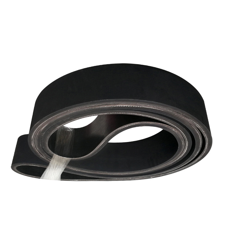
The conveyor belt is composed of surface adhesive, core, and layer glue. In addition, a layer of buffer cloth can be added to the use of high drop impact to make it more impact-resistant.
The surface adhesive
With natural rubber and synthetic rubber as raw materials and in order to enhance wear resistance, crack resistance, aging resistance, and other properties, the surface adhesive has various characteristics such as wear resistance, cutting resistance, heat resistance, flame resistance, cold resistance, acid and alkali resistance, oil resistance, static electricity resistance and so on. Cloth layer core
The cloth layer is composed of natural fiber or chemical fiber alone or a combination of the two, has the same quality after single-step treatment by a mature process, And has good adhesion with rubber. The adhesive layer
The adhesive layer is very important for the adhesive force between the layers of the core of the conveyor belt that is repeatedly flexed. Especially for high-tension conveyor belts, a layer of adhesive with less buckling stress and less fatigue due to internal stress must be used.
Specifications and models can be customized according to customer requirements, with a thickness ranging from 2.0 mm to 8.0 mm.
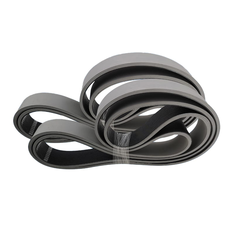
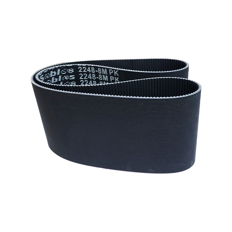
High-speed, smooth, and low-extension transmission and conveying systems, such as textile machinery, woodworking machinery, grinding machinery, ticket vending machines, vegetable cutting machines, etc. Characteristics: High speed and stability, high tensile strength, and low elongation.
The seamless rubber band produced by woodworking machinery can be used for sanding, correcting, and trimming core materials, planing wood boards, laminated boards, plastic laminated boards, and other machines, and can help the surface to be perfectly machined and selected.
Its special technology lies in the manufacturing method and produces the required size jointless belt. We not only strictly control the quality, but also insist on using imported materials in order to make our sander belt have better performance.
All parts of thickness and strength are absolutely uniform.
It has a good linear operation.
High flexibility can be used for small wheel diameters.
It can maintain flatness and non-deformability under working pressure.
The friction coefficient between the bottom of the belt and the plate surface is very low.
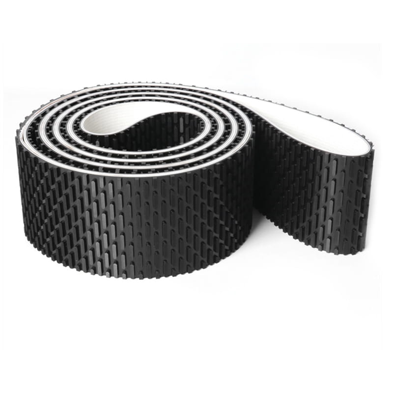
Because the surface layer of the belt is covered with rubber, the adhesiveness is improved and the stability of the conveyor belt is improved.
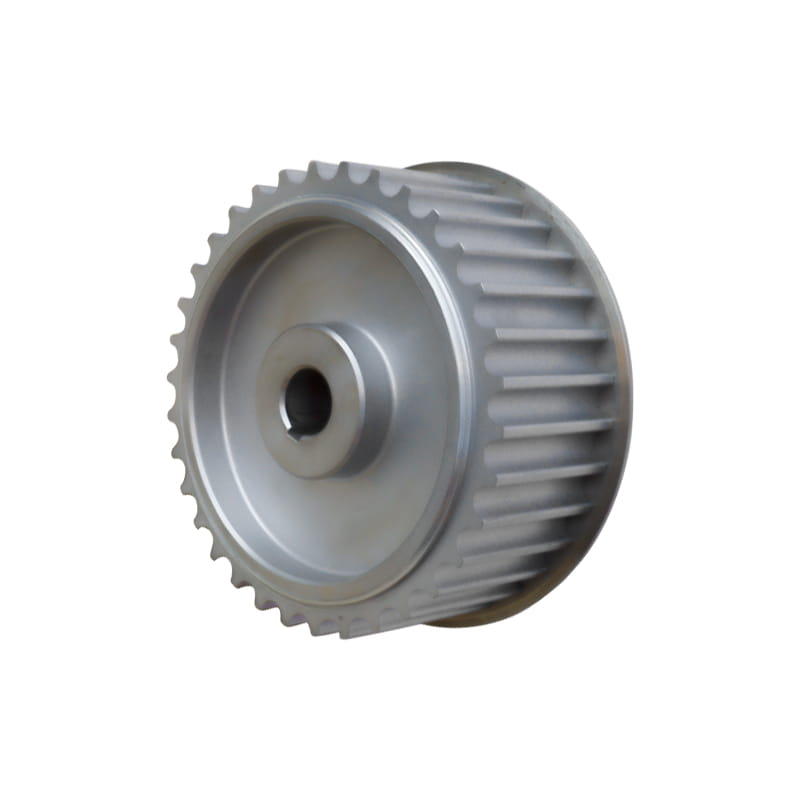
Apply to each field of the synchronous-driven device system. Characteristics:
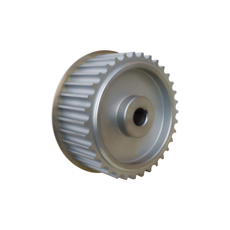
Ensure coordination with the belt, to enhance the accuracy and lifetime of the driven. According to customer requirements, customization optimum driven solution can divided into 45# steel, aluminium alloy, stainless steel, cast iron, nylon, etc, according to the material.
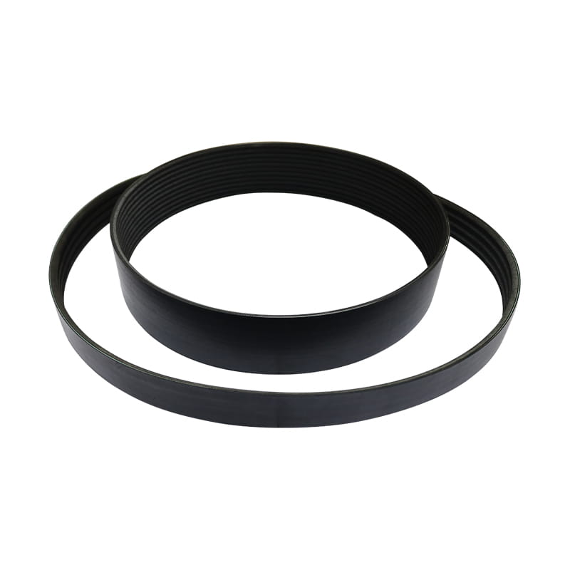
It is suitable for outdoor transmission equipment, transportation equipment, medical equipment, electric tools, household appliances, and sports equipment. Characteristics:
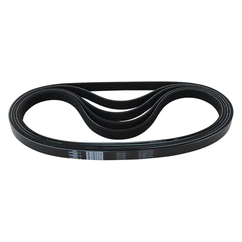
1. The transmission power of the ribbed belt is higher than that of an ordinary V-belt by 30 % when the space is the same.
2. The transmission system of the ribbed belt has a compact structure, and under the same transmission power, the space occupied by
the transmission device is 25 % smaller than that of the common V-belt.
3. The ribbed belt is thin and flexible and is suitable for transmission with a small pulley diameter and high-speed transmission, with belt
speed up to 40m/ s; Small vibration, less heat, and stable operation.
4. The ribbed belt is heat-resistant, oil-resistant, and wear-resistant, with small elongation and a long service life.



 中文简体
中文简体