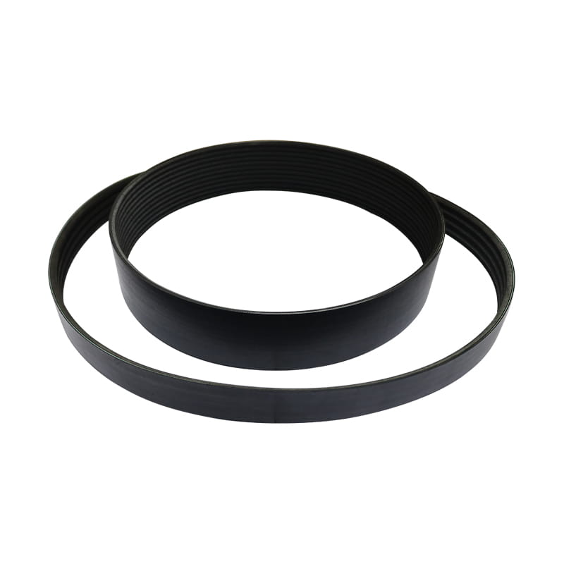
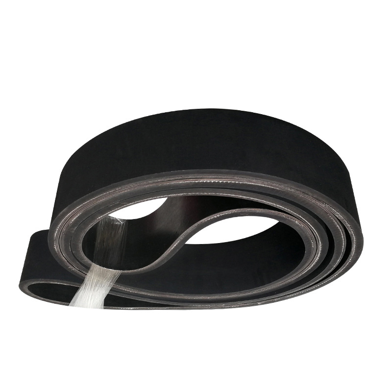
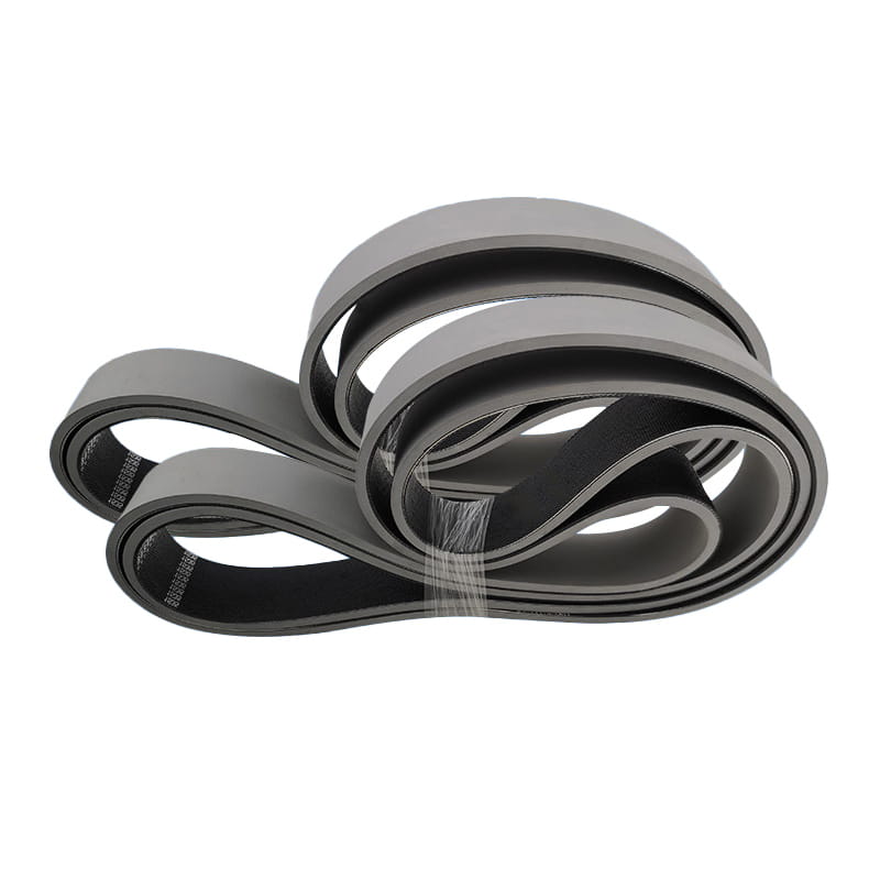
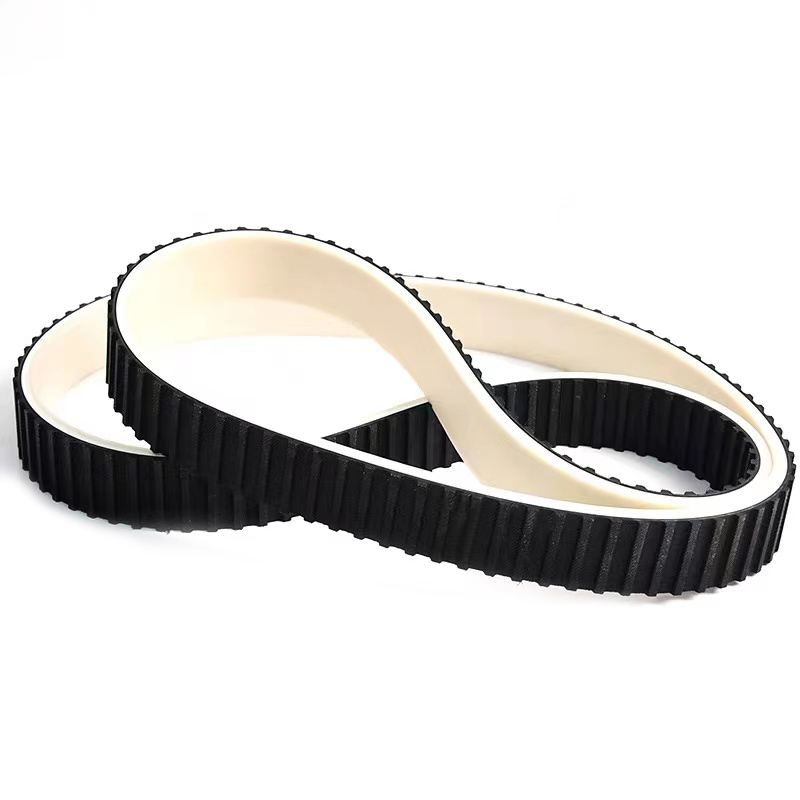
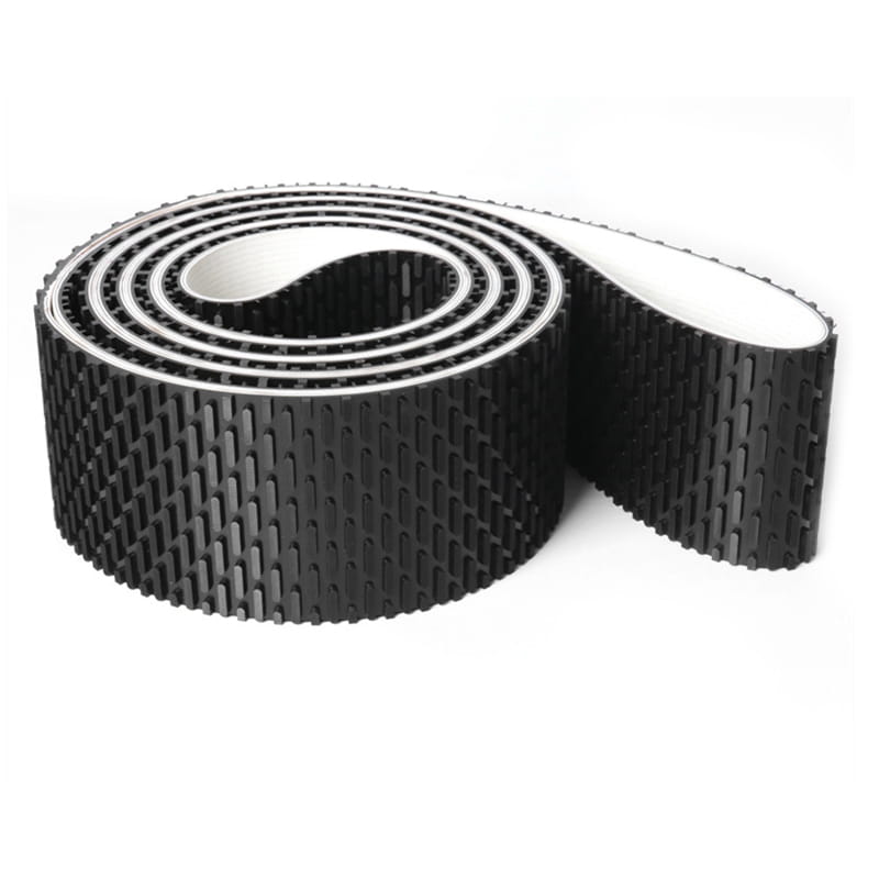
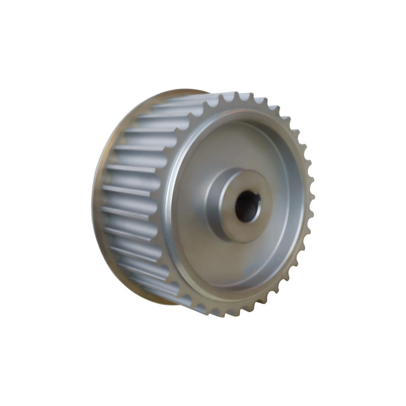
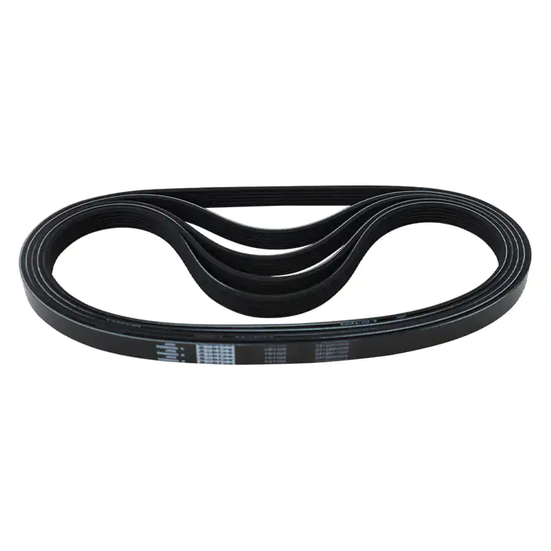
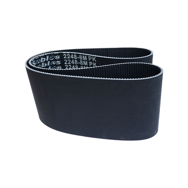
To install Rubber Timing Belts, follow six core steps in sequence: align all sprockets to the manufacturer's timing marks before removing the old belt, lock the sprockets to prevent rotation, route the new belt onto the sprockets starting from the crank without forcing or prying it, seat the belt teeth fully into the pulley grooves, set the correct tension using either center distance adjustment or a tensioner pulley, and verify timing alignment by rotating the drive two full revolutions before final startup. Pfeifer Industries states that any degree of misalignment will result in some reduction of belt life, and that misalignment of timing belt drives should be less than 1/4 degree or 1/16 inch per foot of linear distance (Source: Pfeifer Industries, Timing Belt Installation Guidelines). Getting alignment and tension right at installation is what determines whether the belt performs to its full rated service life or fails prematurely.
Tools Required Before You Begin
Having the correct tools assembled before the job starts prevents errors caused by improvisation and protects both the belt and the drive components during installation.
- Socket set and torque wrench: required to remove and reinstall all fasteners at manufacturer-specified torque values, particularly tensioner bolts and crankshaft pulley bolts
- Camshaft locking tools or sprocket locking pins: these application-specific tools lock the camshaft and crankshaft sprockets in the correct Top Dead Center position, preventing rotational shift when the old belt is removed (Source: Engineer Fix, How to Fix a Timing Belt: Step-by-Step Replacement)
- Crankshaft pulley puller or harmonic balancer puller: needed on many engines where the crankshaft pulley press-fits onto the crank nose and cannot be removed by hand
- Belt tension gauge: a pencil-style deflection gauge or sonic tension meter for industrial drives; for automotive applications, a manufacturer-specified tensioner setting tool or automatic tensioner with retaining pin
- Straight edge or laser alignment tool: used to verify that both sprockets lie in exactly the same plane before the new belt is fitted
- Touch-up paint or marker: to highlight timing marks on sprockets and engine block for easier visibility during installation, as recommended by Dayco's timing belt installation guidance (Source: Dayco, Top 3 Timing Belt Tools and Tips)
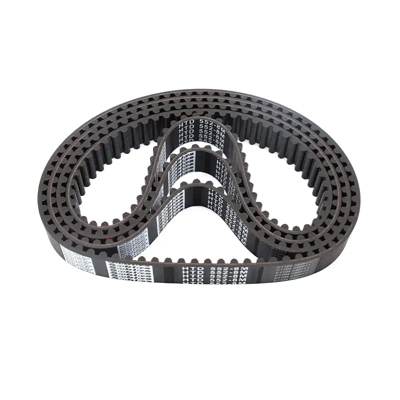
For industrial drive systems rather than automotive engines, the service manual for the specific machine or Pfeifer Industries' timing belt installation guidelines recommend confirming belt tooth profile compatibility, such as HTD, AT, T, or XL, with the sprocket before beginning, since profiles are not interchangeable between pulley types (Source: Puteken, How to Tighten Industrial Timing Belt Step-by-Step Guide).
Step-By-Step Installation Process
Step 1: Align To Top Dead Center And Lock Sprockets
The most important step before touching the old belt is to align the engine or drive system to the manufacturer's reference position. For automotive engines, this means rotating the crankshaft slowly until the timing marks on both the crankshaft and camshaft sprockets align precisely with their corresponding marks on the engine block or cylinder head (Source: Engineer Fix, How to Fix a Timing Belt). Once aligned, install the camshaft and crankshaft locking tools to prevent rotational movement while the belt is off. For industrial drive systems, mark the starting position of both the driver and driven pulley in relation to a fixed reference before releasing tension.
Dayco's installation guidance recommends using touch-up paint to highlight the timing mark locations so they remain clearly visible throughout disassembly and reassembly, particularly on older engines where factory marks may have faded (Source: Dayco, Top 3 Timing Belt Tools and Tips).
Step 2: Remove Old Belt, Tensioner, And Idler Pulleys
With sprockets locked, release the belt tensioner to create slack, then carefully lift the old belt off the sprockets without prying. Engineer Fix's replacement guide advises avoiding prying or forcing the old belt off, since doing so can damage pulley teeth or flanges (Source: Engineer Fix, How to Replace a Timing Belt: Step-by-Step Instructions). Remove and inspect the old belt for the actual failure mode, since cracking, glazing, or missing teeth each indicate different root causes that need to be corrected before fitting the new belt. Replace the tensioner and idler pulleys at the same time as the belt, since their bearings accumulate the same wear hours and replacing them together avoids repeating the full job prematurely if a bearing fails soon after the belt is fitted.
Step 3: Clean Pulley Surfaces And Check For Contamination
After the old belt is removed, thoroughly clean all exposed sprocket and pulley surfaces to remove oil residue, debris, and old rubber particles. Engineer Fix's replacement procedure specifically states that all exposed pulleys and the area surrounding the sprockets should be cleaned after the old belt is removed (Source: Engineer Fix, How to Replace a Timing Belt). Check for oil or coolant leaks from seals at the camshaft, crankshaft, and water pump. Any active leak must be repaired before the new belt is fitted, since oil contamination rapidly degrades rubber compound and adhesion between the rubber body and the tensile cords, causing premature delamination and failure.
Step 4: Route The New Belt Without Forcing
Route the new rubber timing belt onto the sprockets starting from the crankshaft sprocket, then working toward the camshaft sprockets. Keep the section of belt between the drive and driven sprockets that will carry the load taut, while leaving slack near the tensioner side. Engineer Fix's installation guidance is explicit on this: the belt must be slid onto the sprockets without forcing or prying, which could damage the internal tensile cords and lead to premature failure (Source: Engineer Fix, How to Replace a Timing Belt). Before any tensioning, confirm that the belt teeth are fully and evenly seated in the pulley grooves across the full belt width, with no partial engagement on either edge of the pulley.
Step 5: Set Tension Correctly
Correct tension is the most technically demanding step of the installation process, and both undertensioning and overtensioning cause accelerated failure. Pfeifer Industries documents this clearly: if measured deflection force is less than the required value, lengthen the center distance; if greater, shorten it. After the belt is properly tensioned, lock down the center distance adjustments and recheck sprocket alignment (Source: Pfeifer Industries, Installation: Timing Belt Tensioning Guide). The preferred method for industrial drives is the sonic tension meter, which strums the belt like a guitar string and measures the vibration frequency to calculate tension accurately without disturbing the belt span (Source: Pfeifer Industries). For automotive automatic tensioners, pull the retaining pin to allow the tensioner to apply its predetermined spring force against the belt after routing is complete.
Step 6: Verify Timing And Rotate Before Startup
After tension is set, remove the locking tools and rotate the drive manually through two complete revolutions in the normal operating direction. This allows the belt to fully seat into the pulley grooves and the tensioner to reach its final operating position (Source: Engineer Fix, How to Put a Timing Belt Back On and Set Tension). After two full revolutions, return to the reference timing position and re-verify that all timing marks align exactly. If marks are even one tooth position off, the belt is mistimed and the entire installation must be repeated before startup. For industrial drives, Pfeifer Industries additionally recommends rechecking belt tension and alignment after eight hours of initial operation to ensure the drive has not shifted (Source: Pfeifer Industries, Timing Belt Installation Guidelines).
Pulley Alignment: The Most Common Source Of Belt Failure
Pfeifer Industries identifies drive alignment as one of the most common causes of drive performance problems, noting that misaligned drives show symptoms including uneven belt wear, edge wear, noise, vibration, and reduced belt life (Source: Pfeifer Industries, Timing Belt Installation Guidelines). Two types of misalignment cause different failure patterns.
Parallel Misalignment
This occurs when the driver and driven shafts are parallel but the pulleys lie in different planes, offset from each other along the shaft axis. The belt tracks toward the low side and wears against the pulley flange, causing progressive edge damage and eventual belt failure. Checking for parallel misalignment uses a straight edge held against the face of both sprockets: both sprocket faces must contact the straight edge simultaneously at both the top and bottom contact points.
Angular Misalignment
Angular misalignment occurs when the two shafts are not parallel. Pfeifer Industries explains the failure mechanism: the tensile cords on the high-tension side of an angularly misaligned drive are overloaded, causing edge cord failure that propagates across the belt width, combined with high belt tracking forces that cause excessive edge wear (Source: Pfeifer Industries, Timing Belt Installation Guidelines). The tolerance limit is firm: misalignment must be kept below 1/4 degree or 1/16 inch per foot of linear distance. Any angular misalignment beyond this limit produces accelerated belt degradation that is not accounted for in the belt's standard load rating.
Two Tensioning Methods For Industrial Rubber Timing Belts
Industrial rubber timing belt drives use two primary tensioning methods depending on the machine's design and the space available for adjustment.
Center Distance Adjustment (Preferred Method)
Moving the motor base or driven pulley mounting along linear guides increases the center distance between the two pulleys, applying tension to the belt. Puteken's industrial tensioning guide confirms that this is the recommended primary method because it provides uniform belt tension and accurate pulley alignment while keeping both shafts parallel (Source: Puteken, How to Tighten Industrial Timing Belt Step-by-Step Guide). Once the correct tension is reached and confirmed by measurement, all mounting bolts are tightened to prevent the center distance from changing during operation. Pfeifer Industries adds an important operational note for rubber timing belts specifically: due to their high resistance to elongation, there is no need to re-tension a rubber timing belt after the initial tensioning, unlike elastomeric drive belts that require re-tensioning after an initial seating period (Source: Pfeifer Industries, Timing Belt Installation Guidelines).
Inner Tensioner Pulley Method
When center distance adjustment is not possible due to machine design constraints, a tensioning pulley installed inside the belt loop on the slack side provides the required tension by pressing outward against the inner belt surface. Puteken advises that the tensioner must press evenly on the belt without interfering with pulley teeth engagement, and that the tensioner is only suitable where center distance adjustment is unavailable rather than as a first preference (Source: Puteken, How to Tighten Industrial Timing Belt Step-by-Step Guide). Overtensioning through an inner tensioner creates a concentration of bending stress at the tensioner contact point that can accelerate fatigue in the tensile cords over time.
| Method |
How It Works |
When To Use |
Key Note |
| Center distance adjustment |
Motor or driven pulley moved along linear guide to increase center distance |
Primary method, always preferred |
Maintains shaft parallelism and even tension across full belt width |
| Inner tensioner pulley |
Idler pulley presses against inner face of belt on slack side |
Only when center distance adjustment is not available |
Risk of bending stress concentration at contact point if overtensioned |
| Automotive spring tensioner |
Pre-loaded spring or hydraulic piston applies constant force via retaining pin release |
Automotive engines with automatic tensioner design |
No manual adjustment needed; verify indicator pointer is within range after two rotations |
Installation Mistakes That Shorten Belt Life
Most premature rubber timing belt failures in the field trace back to one of a small number of installation errors rather than defects in the belt itself.
- Prying the belt onto sprockets: forcing or levering the belt over pulley teeth damages the internal tensile cords without leaving visible external marks, creating internal weak points that fail under load weeks or months later (Source: Engineer Fix, How to Replace a Timing Belt)
- Overtensioning: applying more tension than the manufacturer specifies stresses the tensile cords, accelerates bearing wear on the motor and driven machine shafts, and can cause belt failure in less than half the expected service life; Puteken confirms that over-tightening increases stress on belt cords, bearings, and shafts, leading to premature failure (Source: Puteken, How to Tighten Industrial Timing Belt)
- Undertensioning: insufficient tension allows the belt teeth to jump over pulley teeth under sudden load changes, causing immediate loss of synchronization and in automotive engines can bend valves on interference-design engines (Source: Engineer Fix, How to Put a Timing Belt Back On and Set Tension)
- Installing a belt while oil contamination is present: any residual oil from camshaft or crankshaft seals penetrates the rubber compound and causes rapid softening and delamination of the tooth face; all leaks must be repaired and surfaces cleaned before fitting the new belt
- Skipping the post-installation verification rotation: without rotating the drive two full revolutions and re-checking timing marks, a one-tooth misinstallation will not be caught until engine startup, at which point the damage in an interference engine is immediate and catastrophic
Choosing The Right Belt Before Installation Begins
Correct installation technique delivers its full benefit only when the belt specified is the right one for the application. Using a belt with the wrong tooth profile, the wrong pitch, or an insufficient tensile cord specification for the drive's load will produce premature failure regardless of how carefully installation is carried out.
- Confirm the tooth profile matches the sprocket exactly: HTD, AT, T, XL, and other profiles have different tooth geometry and are not interchangeable even if the pitch length appears similar
- Confirm the pitch and number of teeth are correct for the sprocket combination, since even a one-pitch difference in belt length will prevent correct tensioning
- Match the belt width to the sprocket face width, since a belt wider than the sprocket will ride off the flange, and a belt narrower than the sprocket will not carry the rated load
- For applications with high shock loads, specify aramid tensile cord construction rather than standard fiberglass, since aramid's higher elongation resistance prevents tooth jumping under sudden torque spikes
The KML Rubber Timing Belts range covers standard tooth profiles in the widths, pitches, and tensile cord materials needed for both automotive and industrial drive applications, providing a specification-accurate starting point for any installation where belt selection and installation precision both determine how long the drive operates reliably.



 中文简体
中文简体