A dropped key, a scored hub, and a belt that starts climbing the flange two weeks after a rebuild. That sequence is usually blamed on the belt, but the root cause sits in the pulley keyway. When a pulley is pulled off a shaft for maintenance, the key is the first part to go missing, and the replacement is too often picked by eye from whatever is loose in the spare parts bin. The difference between a correctly fitted key and a loose one is measured in hundredths of a millimetre, yet it decides whether the connection survives a year of torque reversals or fails within a month.
The short answer first: a pulley keyway is a machined slot cut along the bore of the hub, matched by a slot on the shaft, that together hold a key which transfers torque and fixes the angular position of the pulley. Get the width, the depth and the surface finish right and the key becomes the cheapest and most predictable component in the drive train. Get them wrong and the key becomes the fuse that blows, occasionally taking the shaft with it.
What a Pulley Keyway Actually Does
This one slot does three jobs, and it performs them with no redundancy at all.
Torque transfer. The key, not friction, carries the working load between shaft and hub.
Angular location. The position of the pulley teeth or grooves on the shaft is fixed by the keyway, not by the fit of the bore.
Assembly reference. A machined slot gives maintenance staff a positive orientation point, so the hub cannot be refitted a few degrees out.
The torque itself travels through the key flanks into two narrow contact strips, one in the shaft and one in the hub. Every newton metre of load passes through those strips, while the corners of the slot concentrate stress and the slot depth removes material from the section that resists bending. Those two effects explain why dimensional standards cap the shaft-side depth t1 and keep it slightly smaller than the hub-side depth t2: the shaft is the part nobody wants to replace, so the keyway is positioned to keep more material on the shaft side.
On a synchronous pulley the keyway also sets timing. If the hub keyway is cut a few degrees away from the tooth pitch datum, the belt teeth meet the pulley grooves at the wrong point in the cycle, and the result shows up as uneven wear on one flank of the tooth rather than as an obvious fault. The discipline that applies to the pulley groove applies to the hub slot as well, which is why the tooth profile of a timing belt and the pulley groove it runs in should be treated as one system rather than two parts bought separately.
On metric drawings the key and the keyway are not free choices. The shaft diameter selects a row, and the row dictates the key cross section, the shaft groove depth and the hub groove depth. The common mistake is to size the groove from whatever key is in the drawer and ignore the depth, because an over-deep shaft groove removes load-bearing section from a shaft that is already working under alternating torque.
Nominal key and keyway dimensions for common shaft diameters, following the DIN 6885 series. Always confirm against the drawing or the purchase standard in force.
Shaft diameter range (mm)
Key size w x h (mm)
Shaft groove depth t1 (mm)
Hub groove depth t2 (mm)
6 to 8
2 x 2
1.2
1.0
Over 8 to 10
3 x 3
1.8
1.4
Over 10 to 12
4 x 4
2.5
1.8
Over 12 to 17
5 x 5
3.0
2.3
Over 17 to 22
6 x 6
3.5
2.8
Over 22 to 30
8 x 7
4.0
3.3
Over 30 to 38
10 x 8
5.0
3.3
Over 38 to 44
12 x 8
5.0
3.3
Over 44 to 50
14 x 9
5.5
3.8
Over 50 to 58
16 x 10
6.0
4.3
Over 58 to 65
18 x 11
7.0
4.4
Over 65 to 75
20 x 12
7.5
4.9
The width tolerance is the part that genuinely needs to be written on the drawing. Keys are normally supplied to h9, and the fit is decided by the two grooves. The shaft groove is usually held tighter than the hub groove, because damage to the shaft is far more expensive to repair. How tight depends on how the pulley is assembled: a sliding fit needs clearance to be pushed on by hand, while a tapped-on or press fit can be tighter but becomes harder to strip during maintenance.
Why Fit Clearance Matters More Than Nominal Size
A nominal 8 mm key in a nominal 8 mm groove tells you almost nothing about how the joint will behave. What matters is the clearance left between the key flank and the groove wall after machining. Once that clearance is large enough for the key to move under load, the key starts rocking inside the slot every time the torque reverses, and fretting wear begins on the flanks.
The values above are indicative, used to show a trend rather than to serve as a measurement table. The curve begins almost flat, which means a small amount of clearance at the tight end of the range costs very little life. Past the knee of the curve the drop becomes steeper, so each additional 0.02 mm of clearance takes away more life than the previous increment. The practical reading is that loosening the hub groove by half a tolerance grade to make assembly easier moves the drive along the curve, and where that lands matters. A lightly loaded conveyor roller running in one direction tolerates a looser fit than a printing machine main shaft that reverses torque constantly. That is the reason the keyway width tolerance belongs on the drawing rather than in the hands of the machinist at the bench.
How Keyed Pulleys Fail in Service
The order of failure modes is remarkably consistent from one plant to the next, and it rarely starts with the key breaking.
This ranking reflects what teardowns in maintenance workshops most often reveal, not what a laboratory fatigue rig produces. Fretting on the key flanks sits at the top because it develops slowly and is almost never noticed during a routine walk-round inspection. Shearing and hub corner cracking are events that follow it, because once the fit has loosened the impact load concentrates at the corners of the slot. Shaft groove deformation ranks fourth and is the least welcome finding of all, since a scored shaft costs far more to replace than a key. A pulley slipping on its shaft is simply the final state, and by then the belt teeth are being chewed as well. The lesson is consistent: most keyed pulley failures trace back to a loose fit rather than to insufficient material strength.
Hub Material Changes the Keyway Limit
The key is almost always the harder part, so in practice the load is limited by the softer of the two grooves. That makes hub material a direct design decision rather than a cosmetic one.
An aluminium hub behaves differently from cast iron or steel because the groove resists the key load through the shear strength of the hub material itself. A steel hub reaches roughly twice the capacity of grey cast iron, and that gap explains why heavily loaded drives rarely use aluminium pulleys. Ductile iron sits between the two and is the compromise most machine builders settle on when cost and strength both matter. Sintered metal hubs are cheap to produce but score around seventy on this scale, which suits small, lightly loaded pulleys rather than main drive positions. When an aluminium pulley cannot be avoided, the usual fix is to lengthen the key engagement or move the torque path to a clamping element instead of a key. Select the hub material for shear capacity first, then weigh mass and cost against that baseline.
Machining Options for the Hub Keyway
The slot in the hub can be produced in several ways, and the choice changes both the achievable accuracy and the economics of the order. The comparison below scores two common production routes against each other on the criteria that actually decide a quotation.
This radar comparison scores the same hub keyway produced by two different processes, with each axis normalised from zero to one. Broaching rates high on dimensional accuracy, surface finish, cutting speed and internal keyway access, because a single pass of a form tool produces the slot in one movement. Its weak point is small batch flexibility, since the broach itself is made and resharpened for one keyway width and depth combination. Slotting behaves in the opposite way: tooling entry cost is lower, and a single hub or a short batch is far easier to accommodate, but the process is slower and the finish is normally a step behind broaching. Wire cutting and milling sit between the two and are practical for repair work, where ordering a new broach for one pulley makes no sense. The decision normally comes down to volume: if annual output justifies the tooling, broaching is the sensible default, and below that threshold slotting or wire cutting is the more realistic route.
Assembly and Inspection Checklist
Most keyway problems are created during the ten minutes it takes to refit a pulley. A short sequence of checks removes nearly all of them.
Measure the width of the shaft groove and the hub groove with a caliper or bore gauge, and compare the readings with the tolerance band on the drawing instead of judging the fit by feel.
Check that the key sits at the correct depth in both grooves. There should be a small gap between the top of the key and the bottom of the hub groove, never a tight contact.
Deburr the groove edges and remove any rolled-over metal. A single raised burr is enough to tilt the key in the slot.
Trial fit the pulley on a clean, dry shaft. Scoring marks on the bore or the shaft mean the fit is too tight for the intended assembly method.
Rotate the hub so the keyway lines up with the shaft groove before pushing it on, and never drag the pulley into place with the fastening screw.
Tighten the set screw or clamping element to the specified torque, then recheck the tooth phase against the belt if the pulley is a synchronous type.
Recheck radial runout after the first running hours, and add the reading to the routine maintenance record.
A pulley keyway is an unremarkable feature, a narrow slot in a piece of metal, yet it carries the torque and holds the angular position that the whole drive depends on. Give it a defined width and depth tolerance, choose the fit according to how the pulley will be assembled, and measure before fitting rather than after. A keyed connection prepared that way rarely becomes the first thing to fail on the machine.
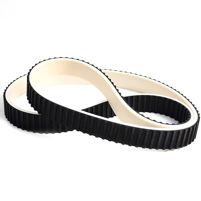
For teams replacing a pulley or designing a new drive, sourcing the pulley and the belt from the same supplier keeps the bore, the keyway and the tooth pitch on one drawing datum. Jiangxi Kangqi Industrial manufactures rubber timing belts, PU timing belts and matching synchronous pulleys, with dimensional records available alongside the test reports, so the hub fit and the tooth profile are settled together rather than in two separate conversations.
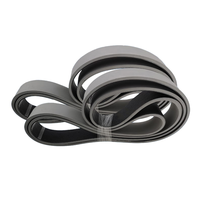
The conveyor belt is composed of surface adhesive, core, and layer glue. In addition, a layer of buffer cloth can be added to the use of high drop impact to make it more impact-resistant.
The surface adhesive
With natural rubber and synthetic rubber as raw materials and in order to enhance wear resistance, crack resistance, aging resistance, and other properties, the surface adhesive has various characteristics such as wear resistance, cutting resistance, heat resistance, flame resistance, cold resistance, acid and alkali resistance, oil resistance, static electricity resistance and so on. Cloth layer core
The cloth layer is composed of natural fiber or chemical fiber alone or a combination of the two, has the same quality after single-step treatment by a mature process, And has good adhesion with rubber. The adhesive layer
The adhesive layer is very important for the adhesive force between the layers of the core of the conveyor belt that is repeatedly flexed. Especially for high-tension conveyor belts, a layer of adhesive with less buckling stress and less fatigue due to internal stress must be used.
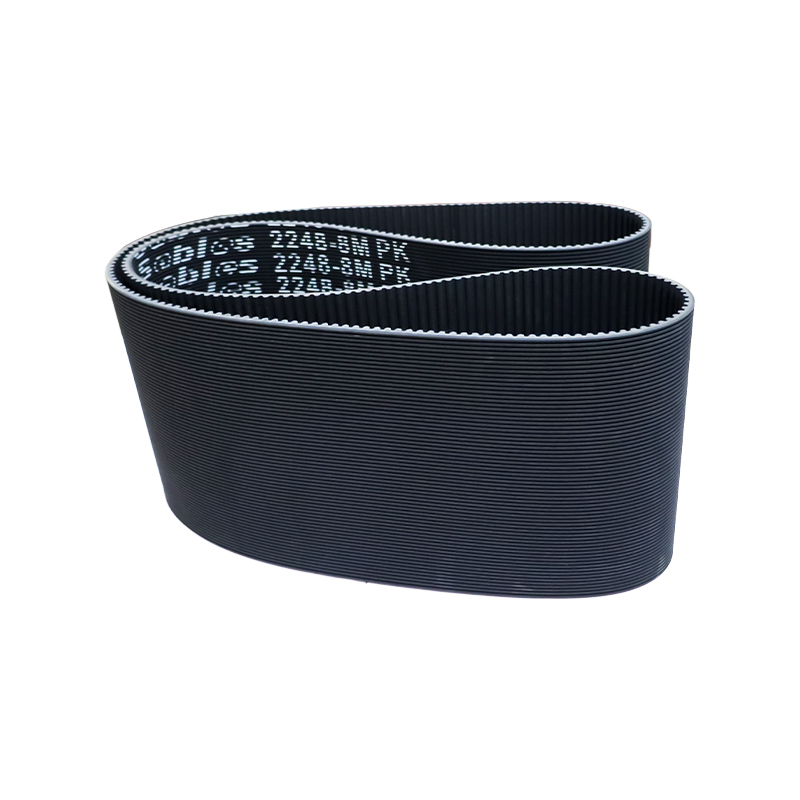
Specifications and models can be customized according to customer requirements, with a thickness ranging from 2.0 mm to 8.0 mm.
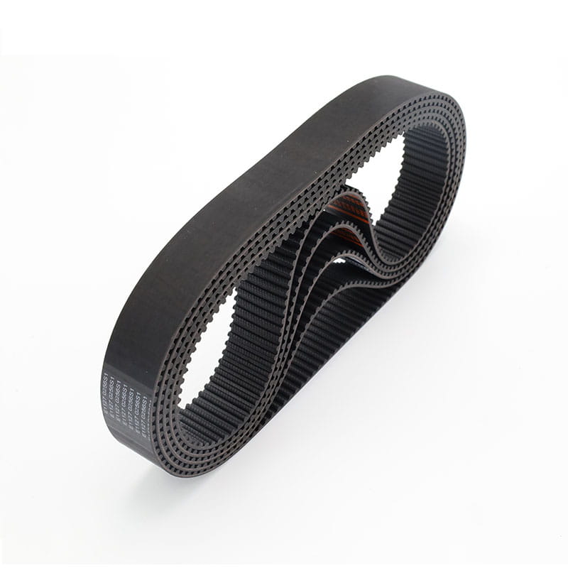
High-speed, smooth, and low-extension transmission and conveying systems, such as textile machinery, woodworking machinery, grinding machinery, ticket vending machines, vegetable cutting machines, etc. Characteristics: High speed and stability, high tensile strength, and low elongation.
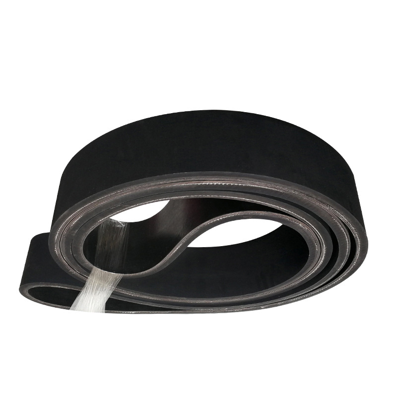
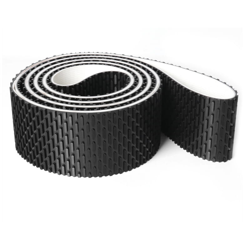
The seamless rubber band produced by woodworking machinery can be used for sanding, correcting, and trimming core materials, planing wood boards, laminated boards, plastic laminated boards, and other machines, and can help the surface to be perfectly machined and selected.
Its special technology lies in the manufacturing method and produces the required size jointless belt. We not only strictly control the quality, but also insist on using imported materials in order to make our sander belt have better performance.
All parts of thickness and strength are absolutely uniform.
It has a good linear operation.
High flexibility can be used for small wheel diameters.
It can maintain flatness and non-deformability under working pressure.
The friction coefficient between the bottom of the belt and the plate surface is very low.
Because the surface layer of the belt is covered with rubber, the adhesiveness is improved and the stability of the conveyor belt is improved.
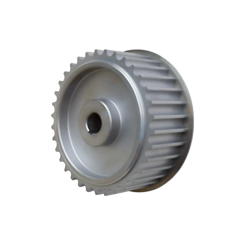
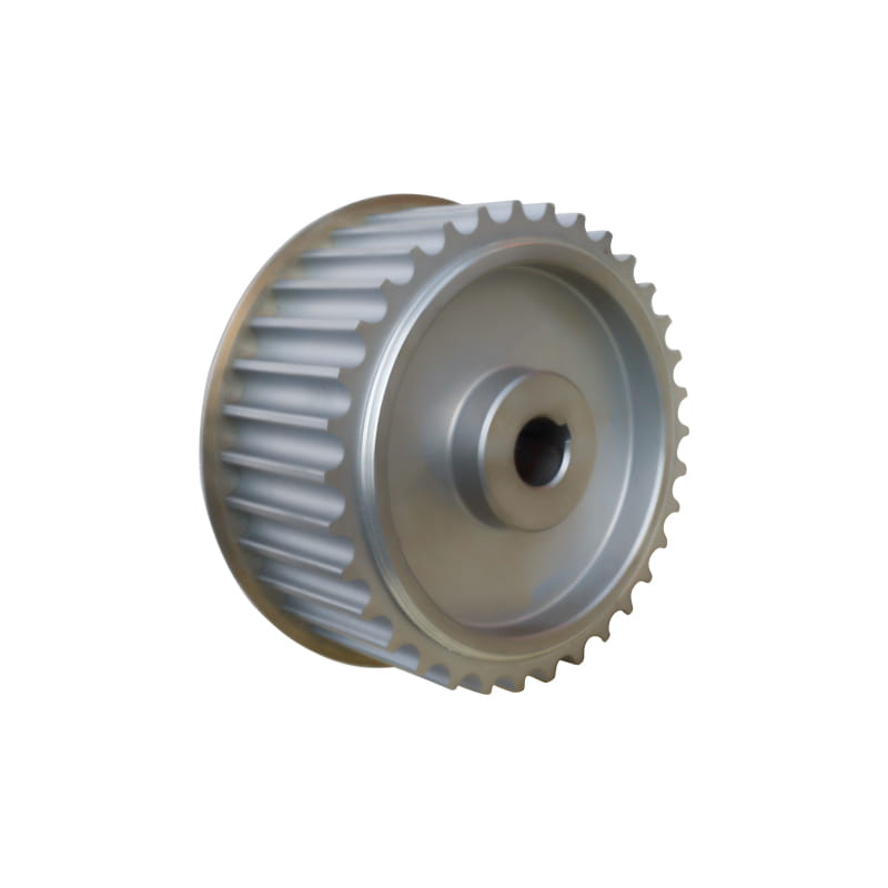
Apply to each field of the synchronous-driven device system. Characteristics:
Ensure coordination with the belt, to enhance the accuracy and lifetime of the driven. According to customer requirements, customization optimum driven solution can divided into 45# steel, aluminium alloy, stainless steel, cast iron, nylon, etc, according to the material.
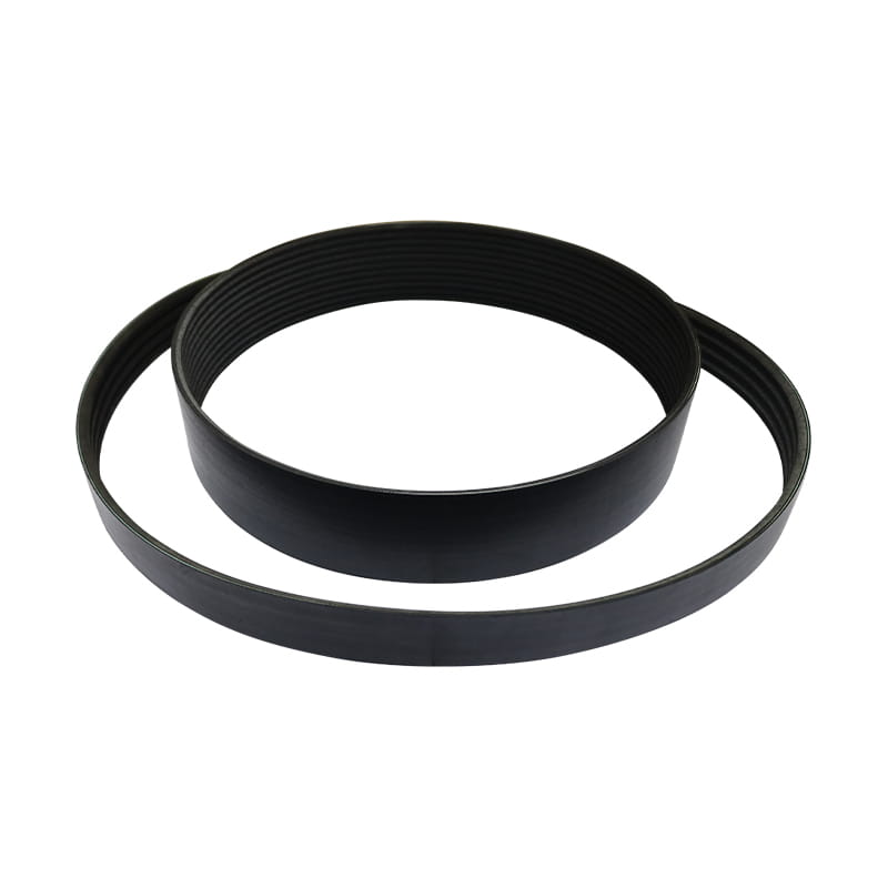
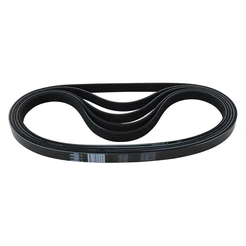
It is suitable for outdoor transmission equipment, transportation equipment, medical equipment, electric tools, household appliances, and sports equipment. Characteristics:
1. The transmission power of the ribbed belt is higher than that of an ordinary V-belt by 30 % when the space is the same.
2. The transmission system of the ribbed belt has a compact structure, and under the same transmission power, the space occupied by
the transmission device is 25 % smaller than that of the common V-belt.
3. The ribbed belt is thin and flexible and is suitable for transmission with a small pulley diameter and high-speed transmission, with belt
speed up to 40m/ s; Small vibration, less heat, and stable operation.
4. The ribbed belt is heat-resistant, oil-resistant, and wear-resistant, with small elongation and a long service life.



 中文简体
中文简体